GRE simple configuration
Published:
Abstract: This is a configuration used in a real setup to solve a network issue to connect two different sub-nets using two routers R1 and R2 on L2 Layer.
What is a L2 Tunnel for ?
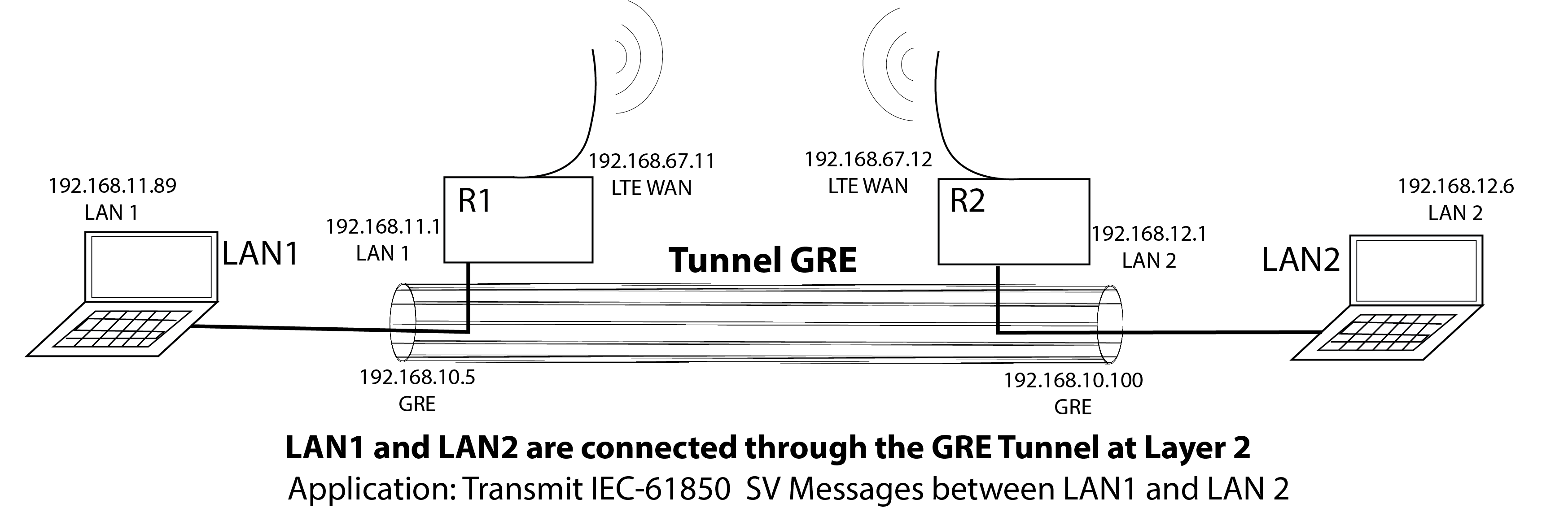
In every communication network, the transport layer plays a fundamental rule. Usually these communication networks are a conjunction of many networks. In parallel, some protocols, such as IEC-61850, transport specific messages with special requirements. For instance, sampled values (SV) message is transmitted over L2 in order to reduce latency using in most of the cases UDP packages. For this setup, it is mandatory to create specific tunnels at L2. One option to handle this type of tunnels is Generic Routing Encapsulation (GRE), other option is to use L2TP.
How to set up a L2 Tunnel ?
The main important thing is to get a good understanding of the networks that you are trying to connect through GRE. Usually the configuration is done between the routers (R1 and R2) that are connected in a specific WAN, the Tunnel will pass over this WAN in order to connect the respective LANs.
Specific information of the layout used in the lab setup.
Here, the following configuration was used to deploy a GRE Tunnel:
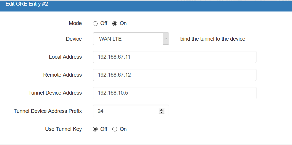
First Router Configuration (R1)
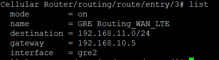
and the following routing police in R1
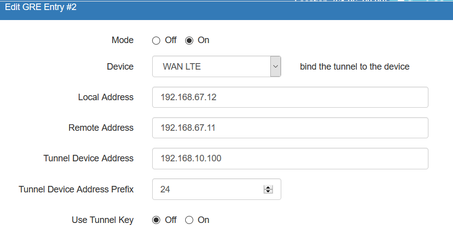
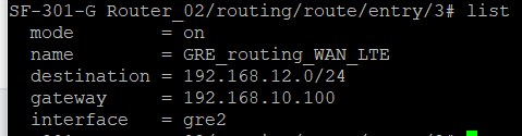
Second Router Configuration (R2)
and the following routing police in R2
Note: Most of the routing commands can be added by CLI or Webinterface configuration of each router. If necessary use Linux commands in the laptop, such as: sudo ip route add PREFIX via address dev interface check in network commands in Linux